Directv Building to Building Relay on Multi Family Projects
For an engineer who is new to designing multi-storey buildings it is of import that they follow a logical sequence through the various stages of the pattern procedure. 6 steps that define this sequence are described below. Rules of pollex are included within each step to help the designer speedily and efficiently get in at a solution that is sensible for a given ready of constraints. In addition, it is of import for the designer to understand some overarching principles of good blueprint – and so that the result is not only sensible but is also 'good'.
[top] Stages of a project
The stages of a construction projection are presented in ISE publication 'Structural design – the engineer'southward function'[1] which may be broadly summarised as follows:
- Projection conception - What information technology'due south for, why is it being proposed, where is it, etc.
- Assembling the information and developing the brief - Understanding the site and context.
- Scheme design - Looking at and developing options.
- Detailed design - Of the various components and elements.
- Information for construction - Drawings, specifications.
- Construction.
Many of these stages include aspects of engineering design. A characteristic of steel framed construction is that the elective parts of the structure are manufactured off-site, with all the quality and speed-on-site benefits that are associated with such a form of construction. An implication of this, however, is that the design must be essentially complete before construction (steelwork fabrication) can brainstorm. It is therefore important that the designer follows a logical sequence, as going dorsum and revisiting earlier pattern decisions, once other parties involved have moved on to designing other parts of the building or manufacturing components, can be unduly expensive.
[top] Basic principles of skilful design
Some basic choices may take a meaning bear upon on the ease, time and cost of both the fabrication and construction of a steel framed multi-storey building. Keeping fabrication and construction in listen from the commencement volition atomic number 82 to the best possible solution. The designer should as well avert over-specification, a trivial example being that corrosion protection is not needed when steel components are used in many internal environments.
[top] Keep it unproblematic and familiar
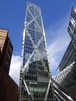
Steel is a versatile material. It tin exist used for single storey buildings, for which its efficiency has helped it reach over 95% market share, and it tin be used for loftier ascension buildings, for which its high strength to weight ratio makes it the but practical choice. Considering of the different ways that steel beams can be configured, steel structures can be used to create floor solutions that are competitive for spans ranging from 6m to over 20m. When choosing betwixt these steel solutions, a bones principle for the designer should always be to keep information technology uncomplicated, and use solutions that are familiar non but to him/her every bit the designer, just volition also be familiar to the fabricator and erector. Complexity and lack of familiarity are more than likely to result in misunderstandings or misuse, and may cost more. Exotic solutions should merely be used for exotic applications that justify the utilize of non-standard and unfamiliar solutions because of the other attributes they bring.
- Unproblematic and circuitous building solutions
-
-
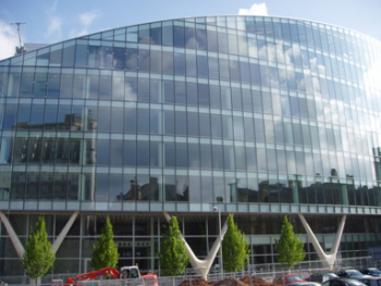
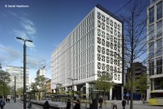
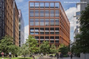
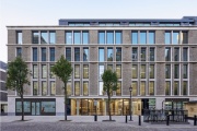
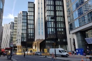
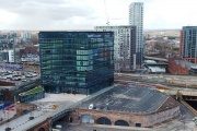
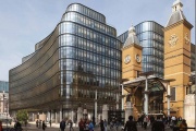
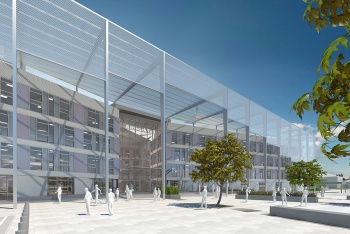
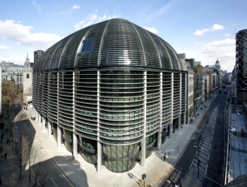
Modern function building in Spinningfields, Manchester
[top] Everyman weight may not be all-time
The impact of steel weight on building cost is interesting as at that place are alien drivers. Some things are quantifiable – in many countries labour is more expensive than materials and then adopting a larger steel section rather than one that needs labour intensive fabrication, for example of stiffeners, tin be more cost effective. Against this argument, using more textile may be associated with greater embodied energy and carbon. But the considerations are more than complex than that because thicker plates also have greater resistance, for example to localised buckling, so the use of larger sections may:
- improve resilience under adventitious loading, making them specially appropriate for key elements to clinch the robustness of a structure against unforeseen circumstances.
- facilitate blueprint for temporary load conditions, this avoiding the need for boosted temporary elements/sub structures during erection.
- permit deliberate over-design, to facilitate change of use in the future and and then extend the lifecycle of a structure.
- crave less fire protection (considering heavier sections have greater expanse/volume), saving on both materials and price.
The extent to which steel weight is minimised will therefore need to be considered on a project-by-project basis taking into account each of the higher up bug.
[top] Standardise
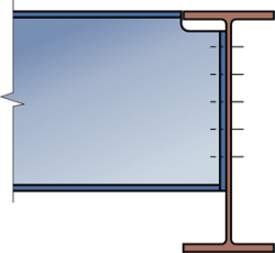
Beam to beam connections - Typical fractional depth cease plate connection between beams
Closely related to familiarity is standardisation. Although the use of standard member sizes is less important than it used to be, given modern ways of modelling and fabrication, there may however exist do good in reducing the number of different member sizes used on a project. This desire for standardisation goes correct downwards to the steel grade and bolt grades and sizes.
Rolled sections should only exist specified in form S355 steel (or higher course) steel to ensure availability as well as performance benefits. However, for the fittings (plates used for connections etc.), many steelwork contractors prefer class S275 steel. Again, a key is to avoid mixing steel grades for components that wait otherwise identical as this facilitates quality assurance.
I of the chief areas where standardisation is beneficial is the joints (or connections as they are traditionally termed in the UK). The use of standard joints means the blueprint process is greatly simplified, for example because resistances are tabulated or software can exist used more effectively, and the detailing volition exist adequate to those who will fabricate and erect the steelwork – standardisation, simplicity, familiarity.
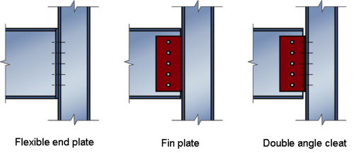
Standard beam-to-column and beam-to-beam simple joints adopt one of the three following options, each with its own particular advantages and areas where information technology is less appropriate:
- Fin plates – peculiarly good from an erection point of view.
- Fractional depth end plates – better than fin plates for connections to column webs.
- Total depth end plates – specially adept for temporary stability and offering significantly greater tying resistance (for robustness) than partial depth plates.
Double angle cleats are no longer normally used for unproblematic connections in the UK.
Standard joints use standard bolts (typically either M20 or M24 Property Class eight.8), and standard plate thicknesses (10, 12 and 15mm). Welded joints are normally restricted to the fabrication shop, where weather condition are much more suitable. Bolted site joints have the additional benefit of facilitating deconstruction.
When detailing joints some other rules of thumb should be followed:
- avoid placing joints in highly stressed regions, and then that the joints remain elementary (thinner connections and less requirement for localised stiffening).
- put site joints (splices) in an accessible identify. Placing splices 1200mm above floors will avoid erectors bending down (good from a CDM point of view), whereas placing them at the location of the intersection betwixt the cavalcade and the beam will minimise the bending moments that volition have to be resisted. Placing them 600mm to a higher place floor level may hence be a adept compromise.
[top] Pay attention to interfaces
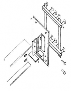
Adjustable bracket for a steel axle to concrete wall connection
The steel frame itself represents merely a pocket-sized function of the overall cost of a building. Even so, how the frame is designed and detailed may bear upon the price of more than expensive components it interfaces with. Interfaces is an area where attending to detail can pay real dividends. There are basically two things to consider at an interface:
- The different components/materials either side of an interface may demand to satisfy dissimilar tolerances. These tolerances may exist a part of what can realistically exist accomplished and/or what is necessary – for case it is not practical to bandage a physical foundation to within 1mm of level, only cladding may need to be placed to within 1mm (and is able to accomplish this) to avoid appearance being compromised.
- An interface between components/materials is often also an interface betwixt design responsibilities. Articulate information transfer is needed and so the designer at each side of the interface understands, and responds to, the requirements of the other side. Recent moves to using a single model, shared between the different blueprint teams involved in a project, should facilitate this information transfer. One such interface is the column base of operations interface where the steelwork design and the foundation design are performed past dissimilar parties.

Column base interface
When different tolerances need to exist accommodated it is much meliorate to attain this through pattern and detailing than through remedial piece of work on site. And so, for example, when steelwork is to exist connected to a concrete core, the use of brackets that allow adjustments in two orthogonal directions (through the use of slotted holes) should exist envisaged from the get-go.
[top] The pattern procedure
Six steps are chosen to split the design procedure into a logical sequence from early on scheme pattern consideration through to detailed design. They comprehend:
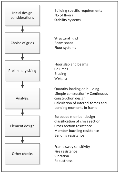
The pattern process
[peak] Step 1: Initial design considerations
Building specific requirements
The basic building shape will normally exist chosen, or at least heavily influenced, by other members of the pattern team. It will often be dictated by site restrictions, be they physical or regulatory such as planning restrictions. Before developing this basic shape into a design the engineer should brand sure he/she is enlightened of any project specific requirements.
Ground conditions may have a fundamental impact on a number of decisions:
- Poor ground favours fewer, probably more than expensive per unit, piled foundations. The wider spacing of the foundations could dictate in a longer spanning structural frame solution.
- If there are any existing foundations on a brownfield site, or underground services to be avoided, these may impact cavalcade positions (perchance resulting in more than widely spaced columns, or an irregular grid pattern).
Information technology is besides worth noting that steel piled foundations (with their number minimised past adopting a long spanning structural frame solution), can hands exist removed at the end of edifice life, avoiding the knock-on effects often plant on redevelopment sites and improving the overall 'sustainability' of the solution.
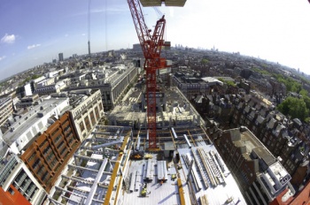
Other aspects of a given site that may favour a certain building frame solution include any admission and peak restrictions. In a congested city center using prefabricated elements may exist attractive, to minimise the number of vehicles needed to bring all the materials to site. If access routes are of limited width, or accept certain other particular characteristics, these may impact on the size of components, or sub structures, that can be delivered. If there is a restriction on the overall tiptop of a building it may favour the employ of shallow floor solutions, even though their spanning ability is less than other steel options, to minimise floor depth and therefore maximise the number of floors (and lettable floor space) that can be accommodated within the overall height.
In add-on to any peculiarities of a given site, at that place may be particular requirements for the building and its use. For some types of use there are specific, published requirements, such every bit the Edifice Bulletins for Instruction buildings and the Wellness Technical Memoranda for Healthcare buildings. Particular requirements may include:
- a naturally ventilated solution may exist required by the customer or the architect.
- the service requirements are dependent on the building use, e.k. hospitals are highly serviced.
- different uses impose unlike requirements for the dynamic behaviour of floors, as what is acceptable in terms of 'bounce' depends on what a room is to be used for.
- the effective planning of the location of lifts, stairs, toilets and vertical distribution of services. These are essential to the operational operation of a building, and just also play a central part in the structural functioning (stability) of the building frame.
If the building is speculative the developer may want maximum flexibility for floor apply, services etc. BS EN 1991-ane-1 [2] presents minimum imposed floor loads for different building uses. For offices, the imposed loading is typically 3kN/m2. In addition, up to 1kN/mii may exist added to cover loading from movable partitions. For storage areas, a higher value of 5kN/kii may be used. Frequently, an imposed load of 5kN/mii is specified in speculative offices to permit for a wide range of client uses. As well as the self-weight of the floors, an additional load of 0.7 kN/thousand2 should be considered for raised floors, ceilings and building services equipment.
Number of floors
To accomplish maximum lettable floor infinite the design should balance the number of floors against flooring-to-flooring meridian, paying attention to the intended building utilize.
The target floor to flooring height is based on a floor to ceiling height of two.5 m to ii.7 m for speculative offices, or 3 m for more prestige applications, plus the floor depth including services. The post-obit target floor to floor depths as shown in the table below should be considered at the concept pattern stage:
| Prestige office | iv - four.2 m |
| Speculative office | 3.6 - 4.0 one thousand |
| Renovation project | three.five - three.nine m |
Shallow floor systems can be helpful for a designer trying to attain the right residue. Although they tend to have a higher price per unit area, the reduced flooring depth may provide the designer with:
- more flexibility to achieve the best compromise between flooring-to-flooring pinnacle, number of floors, and overall building height.
- a ways to reduce building envelope area/cost.
- a means of reducing operational carbon by reducing heat loss through the envelope.
The weight and cost of a structural frame per unit of measurement of flooring area (gross internal expanse) increases with height, because the wind loading increases disproportionately and this has a significant impact on the design of the frame. The increasing cost per square metre is shown for a range of edifice heights in the cost table below.
| Type | GIFA Charge per unit (£/gtwo) BCIS Alphabetize 100 | |
|---|---|---|
| Frame | Depression rising, short spans, repetitive grid / sections, easy access (55kg/chiliad2 steelwork) | 127 - 155 |
| Loftier ascension, long spans, like shooting fish in a barrel access, repetitive grid (90kg/10002 steelwork) | 214 - 242 | |
| High rise, long spans, complex access, irregular grid, complex elements (110kg/one thousand2 steelwork) | 242 - 286 | |
| Floor | Composite floors, metallic decking and lightweight concrete topping | 73 - 114 |
| Hollowcore precast concrete blended floor with concrete topping | 114 - 161 | |
| Fire protection | Manufactory practical intumescent (60 minutes resistance) | 16 - 23 |
| Factory applied intumescent (90 minutes resistance) | 19 - 33 | |
| Portal frames | Big bridge single storey building with low eaves (6 - 8 m) | 95 - 123 |
| Large span single storey edifice with loftier eaves (10 - 13 one thousand) | 108 - 149 | |
Notes:
- 'Piece of cake admission' is for generally unconfined and regular sites where logistics and access arrangements for delivery and erection are unhindered and straightforward.
- 'Circuitous access' is for confined and irregular site plans commonly institute in city centre locations with demanding logistics and access requirements.
Stability system
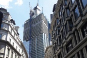
Exoskeleton providing stability to the edifice of the Broadgate Tower, Bishopsgate London
The resistance of a steel frame against horizontal loading tin be achieved in a number of ways. The well-nigh appropriate choice depends on the scale of edifice:
- for depression rise buildings steel bracing is normally used.
- for medium ascent buildings (5 to 15 storeys) either concrete or braced steel cores are used.
- for high rise buildings the use of a concrete core facilitates the structure process as the core assures stability as steelwork erection progresses upwardly the building, tied back to the core. Macro-bracing on exterior faces, an 'exoskeleton', may also be used but substantial temporary works are likely to be needed every bit the final stability system is but complete after a significant number of floors are erected.
Information technology is also possible to provide lateral stability by using a continuous frame – one where at that place is moment continuity between the beams and columns to limit the sway of the frame. However, whilst such a solution would enable, for example, total glazed walls, the connection detailing will be significantly more onerous, every bit will exist the blueprint. Unless in that location are specific building requirements that cannot be satisfied using an alternative, such a solution will be a disproportionately expensive mode of assuring frame stability.
Whatever assures the stability of a frame needs to be able to resist lateral loads applied in two directions, plus a torque. In a braced frame building, the resistance to horizontal forces is provided by 2 orthogonal bracing systems:
- Vertical bracing.
- Horizontal bracing.
Vertical bracing (in vertical planes between lines of columns) provides load paths to transfer horizontal forces to basis level and provide a stiff resistance confronting overall sway As a minimum, three vertical planes of bracing are needed, to provide resistance in both directions in programme and to provide resistance to torsion most a vertical centrality. In practise, more than than 3 are usually provided, for example in the locations shown diagrammatically in the figure right.

At each floor level, bracing in a horizontal plane, (mostly provided by floor plate action), provides a load path to transfer the horizontal forces (mainly from the perimeter columns, due to air current pressure on the cladding) to the planes of vertical bracing.
At roof level, a truss wind girder may be used to provide a horizontal bracing system, if there is no slab. Meet figure left.
[top] Footstep 2: Pick of grids
Having recognised any building specific requirements, decided on the almost appropriate number of floors and, in full general terms, how the frame volition be stabilised against horizontal loading, the designer should start to consider in more particular how the frame will be laid out. The structural grid is defined principally by a regular spacing of columns, with the chief beams spanning between columns, secondary beams spanning between the chief beams, and floor slabs spanning betwixt the secondary beams. Wherever possible the beams are laid out in an orthogonal arrangement to provide rectangular floor plates as this arrangement enables unproblematic orthogonal connectedness details between beams and columns to be adopted.
Flooring grids define the spacing of the columns in orthogonal directions, which are influenced past:
- The planning grid (normally based on units of 300 mm but more typically multiples of 0.vi, 1.2 or one.v yard).
- The column spacing forth the façades, depending on the façades material (typically five.iv to vii.5 chiliad).
- The apply of the internal space, i.due east. for offices or open programme space.
- The requirements for building service distribution (from the building core).
Axle spans typically autumn into the range of 6m to 16m, with over 12m spans being very common on commercial part schemes. Slabs typically span between 3m and 6m. The table below shows typical spans for various commonly used flooring systems.
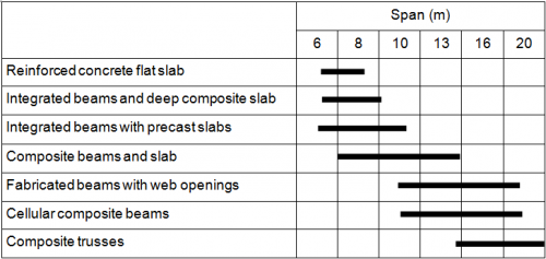
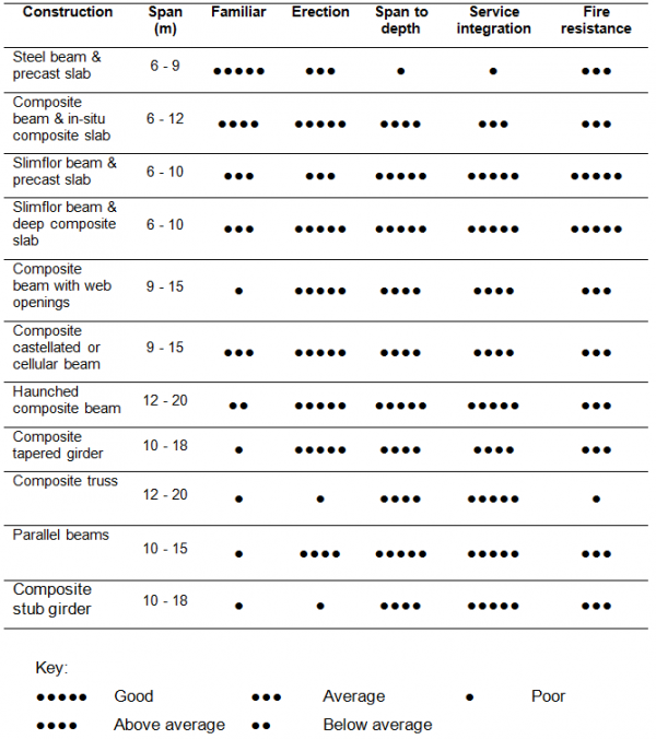
Although opting for a long span solution will increase internal flexibility and maximise the lettable floor space, it should be recognised that spanning ability is just one of the attributes of a given flooring solution. They are also differentiated in terms of fabrication cost, ease of erection, ease of service integration, toll of burn protection, required structural depth for a given span. A designer should make up one's mind on the best overall compromise for a given application, remembering the bones mantra of standardisation, simplicity, familiarity. The table shows the relative merits for common floor systems in multi-storey buildings.
For a building where horizontal services are to be accommodated and integrated within the structural floor depth, deep master beams with holes in their webs (to allow the services to pass through), combined with shallow and therefore short spanning secondary beams is a mutual choice. Alternatively ane may use long secondary and curt chief beams, called and then they are all the same depth.
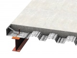
2 of the more mutual composite floor systems are shown below. The benefits of composite slab floors using downstand beams, shallow floors including precast slabs, together with the option of long span beams should exist considered holistically and in the context of the specific projection nether development.
- Types of blended beams
-
Conventional "downstand" axle
-
Integrated beam with deep decking
A broad statement taken from the British Quango for Offices (BCO) Guide to Specification[3] and SCI P365 states that function buildings with columns at vii.5 to 9m centres tend to be most economical. More than specifically, price comparison studies have shown that for three to 4 storey buildings a blended beam and slab option is likely to be the most economical where the optimum grid size for this type of flooring arrangement is typically 7.5m x 9.0m. For a typical eight storey city centre office building, cellular beams and composite slabs were shown to exist the virtually economical. For this size of building a typical optimum filigree size of seven.5m x 15.0m could exist nigh appropriate.
[top] Footstep 3: Preliminary sizing
In one case the grids are established it is possible to estimate preliminary sizes of the beams using some rules of thumb for span to depth ratios.
An estimation of the preliminary sizes of the beams using some rules of thumb for span to depth ratios for the flooring systems mentioned to a higher place is presented in the tabular array.
| Not-blended primary beams | Floor = span/20 Roof = bridge/25 |
| Non-composite secondary beams | Floor = span/25 Roof = span/thirty |
| Composite beams | Span/16 to span/18 (note depth is steel beam plus slab) Long span solutions tend to be shallower, |
The slabs that span between downstand beams are typically 130 to 150mm deep, using C30/37 or LC30/33 physical. When shallow flooring solutions are used the structural flooring depth, including the integrated beams, is typically 300 to 400mm. Typical structural depths (floor to ceiling) are shown in the tabular array.
| Flooring system | Target floor depth (mm) |
|---|---|
| Composite beam construction | 800 – ane,200 |
| Cellular beams (with service integration) | 800 – ane,100 |
| Downstand beams with precast concrete floor slabs | one,200 – 1,450 |
| Shallow floor or integrated beams | 600 – 800 |
Columns
The columns in braced frame multi-storey buildings are usually hot rolled UC sections. Rectangular or round hollow sections can likewise exist used only connections become more complex than when an open cross section is adopted. Typical section sizes for UC columns are given in the table below. The columns are ordinarily continuous over 2 or 3 storeys and the beams discontinuous where they meet the columns.
| Number of floors supported by cavalcade department | Universal Column (UC) serial size |
|---|---|
| 1 | 152 |
| two - iv | 203 |
| iii - 8 | 254 |
| 5 - 12 | 305 |
| ten - xl | 356 |
Note that minor and medium bridge composite floors generally outcome in the same serial size for the columns, but the column weight will exist greater for the medium spans.
Bracing
Steel works well in tension, but only works well in compression if buckling is prevented. So when the bracing is configured and so that information technology simply needs to resist tension (when X-bracing is nowadays inside a bay, ane of the members volition exist in tension when the wind blows one mode, and the other in tension when it blows in the opposite direction) information technology is possible to utilise cross-flats (apartment steel plates equally members). If the bracing must work in compression for example, hollow sections may exist used.
There are other criteria to consider when choosing the form of bracing, across but structural efficiency. Cross-flats may exist useful because they can be hidden within a wall cavity. Thousand-bracing (rather than Ten bracing) leaves room for doorways, although it needs to exist detailed so that it doesn't option up vertical loads from the floors (for which it has non been designed).
Weight of the steel construction
Preliminary sizing considerations should result in a weight of steel similar to that given in the table below. However, at that place may be project specific considerations which could affect the values given in the tabular array which are based on generalised situations.
| Form of Building | Gauge steel quantities (kg/m² floor area) | |||
|---|---|---|---|---|
| Beams | Columns | Bracing | Total | |
| 3 or four storey building of rectangular form | 25–30 | viii–10 | 2–3 | 35–40 |
| 6–8 storey building of rectangular form | 25–30 | 12–15 | 3–v | 40–50 |
| 8–ten storey building with long spans | 35–40 | 12–xv | 3–5 | 50–60 |
| xx storey building with long spans and a concrete core | 40–50 | ten–13 | 1–2 | l–65 |
[top] Step 4: Analysis
Determining the loads
Before the frame can be analysed and the structural members designed it is necessary to determine the magnitude of loads and other actions such as thermal movements, which may outcome in stresses in the structure. The main load types are the self-weight of the structure (and non-structural components), imposed floor loadings, environmental loading including wind and snowfall, and induced additional loads caused past frame imperfections and sway.
| Loading blazon | Area loading (kN/m2) |
| Permanent loads | |
|---|---|
| Steelwork | 0.35 – 0.7 |
| Composite slabs | 1.9 – three.0 |
| Precast slabs | 3.0 – iv.v |
| Partitions | 1.0 |
| Services | 0.25 |
| Ceiling | 0.one |
| Imposed loads | |
| Roof | 0.6 |
| Floors | ii.5 – five.0 |
| Current of air loads | 0.viii – 1.five |
| Snow loads | 0.6 |
The structure will be subject to a number of realistic combinations of these load types (they won't all be at their maximum values simultaneously), considering a Limit State Design philosophy where the frame and its members are designed to satisfy different ultimate and serviceability limit states. The combinations, and different limit states, are defined in the relevant Eurocodes.
Determining the internal moments and forces
One time the loads and preliminary member sizes accept been identified, the structural analysis tin be carried out. This process results in adding of the internal moments and forces the frame members must be able to resist (against which the preliminary sizes can exist checked and the blueprint refined).
The vast majority of steel frames are designed as 'simple'. This means that the beams and columns are assumed to conduct as disconnected members (there is no moment continuity between them). A simple frame does non in itself offer stability against lateral loads. Bracing, or a core, typically fulfils this purpose. Assuming elementary structure offers a number of benefits and results in sure characteristics of the frame:
- It profoundly simplifies assay, with easy derivation of moments and forces for a structure that is 'determinate' (solvable using simple calculations). The stiffness of 1 element does non touch the moments and forces that information technology, and its neighbours, are subject to. The designer should ensure that all chemical element ends are 'released' in the analysis model to reflect this 'simple' philosophy.
- Columns just experience axial force and nominal bending moments due to the eccentricity of beam connections.
- The resulting distribution of moments and forces ways that beams will tend to be bigger and columns smaller than when continuous structure is adopted.
- Joints are less complex, and will tend to use less fabric (thinner plates, no stiffening or need for haunches). But the designer should exist aware of the need to design joints for tying forces to preclude progressive collapse (make the structure 'robust'). Simple joints are causeless not to transfer moment, but if plates are thick enough to provide acceptable tying (axial resistance) will they exist sparse plenty to bend? The behaviour of what is really congenital must always reflect what was assumed in the design. If thick plates are used to reach tying resistance, they may transfer moments into the columns for which those members accept not been designed.
- Blended beams are well suited to simple structure considering they work well in sagging (relying on the concrete slab in compression), but not so well in hogging (slab in tension).
- If trusses are used, it is important to pattern the members to work with 'simple' joints between them. Trusses that require moment transfer between members (internals, chords) are difficult to item and expensive to fabricate (the member size may be governed by the moment connections it tin can adjust). This can cause particular problems in the state of affairs where the frame designer does not also detail the joints (every bit if ofttimes the case in the UK) – the frame designer specifies the sizes of the truss members, but they cannot exist made to piece of work.
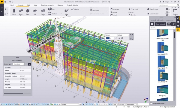
Model of a multi-storey building
(Epitome courtesy of Trimble Solutions (Uk) Ltd.)
If, as an alternative to simple construction, a continuous frame is chosen:
- There volition exist interaction between elements making the frame 'indeterminate' (solution requiring structural analysis using computational software). The relative stiffness of the members affects the distribution of moments and forces around the frame (stiffer the chemical element the greater forcefulness/moment that is attracted to it). As at that place is moment continuity between the members, bracing volition not be needed.
- This interaction means that iteration will be needed to refine member sizes and as a result will require the other members at the connection to be re-designed every bit member angle moments are redistributed accordingly to their relative stiffness.
- Different types of analysis may be envisaged. Typically an elastic analysis is adopted, whereby all the frame members are assumed to retain their initial elastic stiffness and moments and forces are distributed around the frame according to these stiffnesses. A plastic assay recognises that some members (or joints) may be sized so that they reach their resistance limit, at which indicate they maintain that level of load but loose stiffness so that any additional load is carried by adjoining members.
[top] Step five: Element pattern
Having adamant the moments and forces in the frame members and joints it is possible to move on to detailed blueprint. Equally noted above, when a frame is continuous it may be necessary to undertake some iteration because the size of the members affects the moments and forces that are attracted to themselves and their neighbours.
Steel member design is based on the requirements given in BS EN 1993-1-1[4]. Composite member pattern is based on those given in BS EN 1994-ane-1[5]. The overall process in member design for the ultimate limit state (ULS) involves:
- Classification of the cantankerous department.
- Cross-exclusive resistance.
- Member buckling resistance.
- Resistance to combined axial loading and angle, where applicable.
Additionally, members should be designed for whatever relevant serviceability limit states (SLS), normally these relate to deformations (deflections), and response to dynamic loading. For well-nigh multi-storey commercial buildings, straightforward steel structure volition encounter the required vibration operation criteria without modification. For more vibration sensitive applications, such as infirmary operating theatre floors, steel'southward advantages can be captured with additional stiffening applied to the steel frame if required. Long-span applications, for which steel is the only option, take been found to offering very expert vibration damping, despite mutual preconceptions that damping of composite floors is lower than that of concrete structures. The greater mass of the long-span sections which participate in any motion reduces the magnitude of the vibration response.
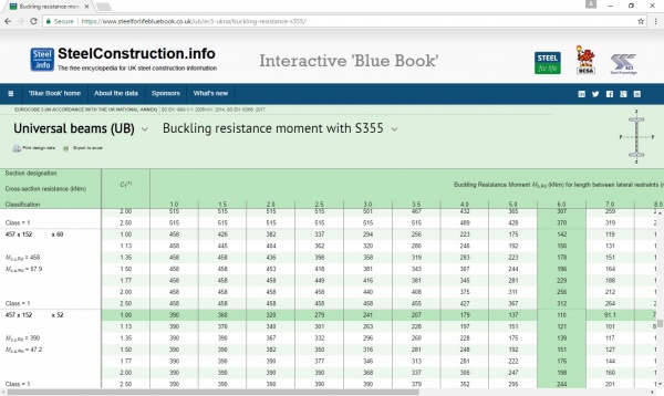
Member design is often completed using software, or by reference to the resistance tables in the 'Bluish Book' (SCI P363). An excerpt from the Blue Volume presenting the buckling resistance moment for UBs is shown below.
The frame designer must remember to consider the various stages of structure as well equally the building in its final state, and the various ULS and SLS checks related to each. Designing the structure to be stiff and strong (and potentially ductile) plenty to satisfy the dissimilar loading and partial completion scenarios will avoid the need for potentially difficult and costly temporary works.
[top] Pace six: Other checks
In addition to checking the frame members for gravity, imposed and wind loads, another verifications must as well be fabricated as they could affect the final size of the members and joints. These other checks include, but are not restricted to, checking for sway sensitivity, fire performance, robustness and acoustics performance.
Sway sensitivity
Even simple braced frames must exist checked for sway sensitivity, as bracing would only forbid all sway if it were infinitely stiff (which clearly nothing is). If the frame proves to be sway sensitive, options (the viability of which will depend on the given building) to pattern for this sensitivity include:
- Increase member sizes so the frame sways less under horizontal loading.
- For a simple frame this means the size of the bracing.
- For a continuous frame the size of the beams and columns affects the frame sway.
- This will not be a viable option for high rising buildings.
- Amplify the starting time order moments and forces to allow for the secondary (second guild) effects that arise every bit the frame sways.
- Behave out a second order analysis to explicitly allow for the secondary effects.
In the braced frame shown in the figure, the bracing extends due to axial tension, allowing the frame to movement laterally, and producing an inclination in the columns, equally shown. As the columns are now inclined, additional horizontal components of force must be resisted past the structure.
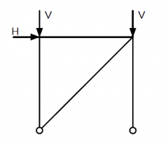 | 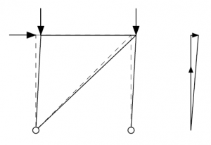 |
The horizontal components of the forces in the columns are proportional to the vertical loads, which demonstrates that frame stability is linked to vertical loads.
BS EN 1993-1-1[4], five.three.ii states that, for frames that are sensitive to buckling, two types of imperfection should be considered:
- Sway imperfections.
- Individual bow imperfections of members.
Burn
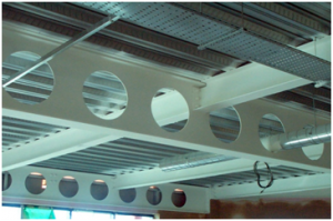
One of the limit states that a designer must consider is fire. Steel loses force every bit it is heated (it will accept lost approximately l% of its room temperature strength at 600oC). In the U.k. the nigh mutual way of dealing with burn down is to protect the members – provide insulation then that the steel temperature remains relatively low. Alternatively a burn engineering approach is possible, whereby the members are designed to resist the loads associated with the fire limit state with a reduced steel strength (every bit a function of the anticipated temperature).
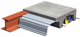
The figure shows steel beams protected from fire by an off-site applied thin film intumescent coating.
Robustness
robustness of a building frame is defined as:
"the ability of a structure to withstand events like burn, explosions, impact or the consequences of human fault, without existence damaged to an extent disproportionate to the original crusade."
This requirement to design and construct a building to have robustness is established from BS EN 1990 [6]. Details of how the requirement should exist met are given in BS EN 1991-1-7[7] with practical guidance being provided past the Institution of Structural Engineers in their publication 'A applied guide to robustness and disproportionate collapse in buildings'[8].
Audio-visual performance
It may be necessary to consider the acoustic performance of the floor and walls, against both impact and airborne audio. This is particularly important for residential, school and infirmary buildings. Sound insulation for both straight and flanking (at junctions) sound is controlled by the post-obit three characteristics:
- Mass.
- Isolation.
- Sealing.
This ways that the construction details of the floors, walls and their junctions in a building are the key to its acoustic performance. Floating floors and suspended ceilings should exist considered – it is not simply a question of adding mass.
In unusual cases there may be other checks to consider, for instance those considering the impact of thermal effects on the frame.
[top] References
- ↑ Structural pattern – the engineer'southward part, September 2011, The Institution of Structural Engineers
- ↑ BS EN 1991-1-i: 2002 Eurocode 1. Actions on structures. General actions. Densities, self-weight, imposed loads for buildings, BSI
- ↑ British Council for Offices Guide to Specification, 2019, BCO
- ↑ 4.0 4.one BS EN 1993-i-1:2005+A1:2014, Eurocode three: Blueprint of steel structures. General rules and rules for buildings, BSI
- ↑ BS EN 1994-ane-1: 2004 Eurocode iv. Design of composite steel and physical structures. Full general rules and rules for buildings. BSI
- ↑ BS EN 1990:2002+A1:2005. Eurocode: Footing of structural design. BSI
- ↑ BS EN 1991-ane-7:2006+A1:2014. Eurocode ane: Deportment on structures. Full general actions. Adventitious deportment. BSI
- ↑ Applied guide to structural robustness and disproportionate collapse in buildings, October 2010. The Institution of Structural Engineers
[top] Further reading
- Steel Buildings, BCSA No. 35/03, Chapter 4, Multi-Storey Buildings
- Steel Designers' Manual seventh Edition. Editors B Davison & G W Owens. The Steel Construction Institute 2012, Chapter 5, Multi-Storey Buildings
- Architectural Design in Steel – Trebilcock P and Lawson R Grand published by Spon, 2004
[elevation] Resource
- SCI P178 Pattern for Construction
- Target Zippo - Guidance on the design and construction of sustainable, low carbon office buildings
- SCI P101 Interfaces - Steel Supported Glazing Systems
- SCI P137 Comparative Structure Cost of Modern Commercial Buildings (2d Edition)
- SCI P166 Design of Steel Framed Buildings for Service Integration
- SCI P300 Composite Slabs and Beams using Steel Decking – Best practise for pattern and construction
- SCI P354 Design of Floors for Vibrations- A New Approach
- SCI P355 Design of Composite Beams with Big Spider web Openings
- SCI P362 Curtailed Eurocode for Blueprint of Steel Buildings
- SCI P363 Steel Building Design: Design Data, 2013
A spider web-based interactive version of the 'Blue Book', is besides available. - SCI P365 Steel Edifice Design: Medium Rise Braced Frames
- Best Practice in Steel Construction: Commercial Buildings
- SCI IEP two Service Coordination with Structural Beams
- SCI IEP iv Supporting Services from Steelwork
- Steel Buildings in Europe - Multi-storey buildings:
- Role 2: Concept design
- Role 3: Deportment
- Part 4: Detailed blueprint
- Role 5: Joint pattern
- Part 6: Fire Engineering science
- Part 7: Model construction specification
- Role 8: Description of member resistance calculator
- Part 9: Description of elementary connection resistance calculator
- Part ten: Guidance to developers of software for the design of composite beams
[height] Encounter Also
- Steel structure products
- Steel material backdrop
- Concept design
- Service integration
- Braced frames
- Continuous frames
- Composite structure
- Floor systems
- Long-span beams
- Trusses
- Portal frames
- Design codes and standards
- Modelling and analysis
- Allowing for the effects of deformed frame geometry
- Fellow member design
- Simple connections
- Moment resisting connections
- Structural robustness
- Steelwork specification
[pinnacle] CPD
- An introduction to Eurocode 3
- Worked examples to Eurocode iii
- Blueprint of floors for vibration
- Design for fire
- Sustainability and steel structure
Source: https://steelconstruction.info/Engineering_students%27_guide_to_multi-storey_buildings
0 Response to "Directv Building to Building Relay on Multi Family Projects"
Post a Comment